Touch Screen (4-wire)
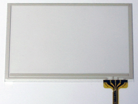
Touch screen become more and more popular. There are a few different technologies around (some of them allow multi-touch), this article deals with the 4-wire resistive touch technology. There are a couple of different screens in different sizes available and I decided to try out SparkFun's 4.3" PSP Touch Screen for $24. It is a good compromise between size and price and it is easy to connect to a bread board with SparkFun's 4.3" PSP Touch Screen Connector Breakout for $4.
SparkFun has also a great USB Touchscreen Mouse tutorial. Practical Arduino has a Touch Control Panel project.
Pin Layout
 |
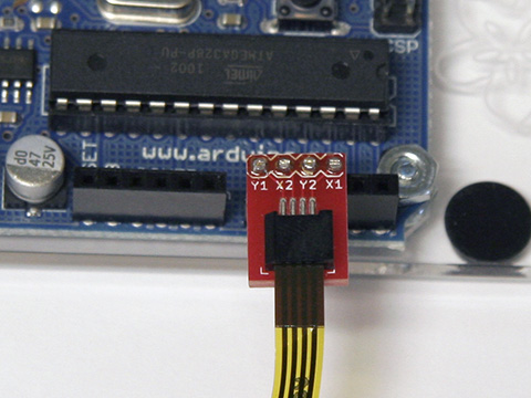 |
| PSP Touch Screen Connector | ATmega168 | Arduino Pin # | Pin Configuration for Reading | ||||
| Pin # | Electrode | Breakout | Port # | Analog | Digital | Read X | Read Y |
| 1 | Top | Y1 | PC0 | 0 | 14 | Input: not used | Output: 1 (5V) |
| 2 | Right | X2 | PC1 | 1 | 15 | Output: 1 (5V) | Input: not used |
| 3 | Bottom | Y2 | PC2 | 2 | 16 | Input: used | Output: 0 (GND) |
| 4 | Left | X1 | PC3 | 3 | 17 | Output: 0 (GND) | Input: used |
Software
All the code be downloaded from here.
Arduino
The Arduino code is pretty easy. It sets the pin configuration for reading x and reads the voltage and then sets the configuration for reading y and reads the voltage. I found that it is important to wait for 1ms between setting up the configuration and the actual read:
/**
 * TouchScreen_test
 *
 * Read position from a 4-wire resistive touch screen.  More information at:
 * https://larsi.org/electronics/TouchScreen/
 */

// the 4.3" PSP Touch Screen with Sparkfun's connector is connected like this
#define PIN_Y1    14 // analog input 0
#define PIN_X2    15 // analog input 1
#define PIN_Y2    16 // analog input 2
#define PIN_X1    17 // analog input 3
#define PIN_READX  2 // analog input 2
#define PIN_READY  3 // analog input 3

// stores the position from the touchscreen
int posX = 0;
int posY = 0;

void setup()
{
  Serial.begin(115200);
}

void loop()
{
  // configuration for reading the x value
  pinMode(PIN_Y1, INPUT);
  pinMode(PIN_Y2, INPUT);
  pinMode(PIN_X1, OUTPUT);
  digitalWrite(PIN_X1, LOW);
  pinMode(PIN_X2, OUTPUT);
  digitalWrite(PIN_X2, HIGH);
  delay(1);                     // let things settle
  posX = analogRead(PIN_READX); // read the X value

  // configuration for reading the y value
  pinMode(PIN_X1, INPUT);
  pinMode(PIN_X2, INPUT);
  pinMode(PIN_Y2, OUTPUT);
  digitalWrite(PIN_Y2, LOW);
  pinMode(PIN_Y1, OUTPUT);
  digitalWrite(PIN_Y1, HIGH);
  delay(1);                     // let things settle
  posY = analogRead(PIN_READY); // read the Y value

  // send position out over serial port
  Serial.print(posX);
  Serial.print(",");
  Serial.println(posY);

  delay(18);                    // wait 18ms (total 20ms)
}
Processing
The Processing code is just a simple demo. It reads the positions from the serial port and keps the last 256 vualues in a ring buffer. The draw() function just draws a circle for all the positions in the buffer.
/**
  * TouchScreen_test
  *
  * visualize the position returned from the Arduino interface
  */

import processing.serial.*;

Serial port;

static final private int LINE_FEED = 10;

static final private int COUNT = 256;

// setup vals from serial
int[] posX = new int[COUNT];
int[] posY = new int[COUNT];
int index = 0;

void setup()
{
  size(960, 540, P2D);
  background(0);
  ellipseMode(CENTER);

  println("Available serial ports:");
  println(Serial.list());

  port = new Serial(this, Serial.list()[1], 115200);

  // clear and wait for linefeed
  port.clear();
  port.bufferUntil(LINE_FEED);
}

void draw()
{
  background(0xFFFFFFFF);

  fill(0xFF336699);
  stroke(0xFF000000);

  for (int i = 0; i < COUNT; i++)
    ellipse(map(posX[i], 0, 1023, 0, width - 1), map(posY[i], 0, 1023, height - 1, 0), 10, 10);
}

// handle serial data
void serialEvent(Serial p)
{
  String data = trim(p.readStringUntil(LINE_FEED));
  if (data != null) {
    String[] data_split = split(data, ',');
    posX[index] = int(data_split[0]);
    posY[index] = int(data_split[1]);
    index = (index + 1) % COUNT;
  }
}