Connectors and Pin Layout
There thousands of cool and interesting plugs and connectors. It is important to come up with a personal standard pretty early, so you can swap components between projects. In an ideal world it would be nice to have a separate GPS for each project, but this not always possible with a $60 price tag (and you probably are not using more than one at a time). It also makes it easy to just replace an older component with a new one or switch one kind of a sensor with another.
Sensors
For most simple sensors we need always 3 wires: GND G, VCC V, and an analog or digital signal S. More complex sensors (like a joystick or an accelerometer) need more pins. Even if we ignore the 180° (reverse plug) there are 3 possible combinations and they are all used by some people:
| # | Layout | Reverse | Who uses it |
|---|---|---|---|
| 1 | G V S |
S V G |
Servo Motors, Bare Bones Board, ArduPilot, Parallax Ping, Mux Shield, GVS Sensor Shield |
| 2 | G S V |
V S G |
Practical Arduino |
| 3 | V G S |
S G V |
SparkFun TEMT6000, SparkFun Microphone |
I decided to use #1, because it is really popular and an accidental reverse connection will not kill anything. I was thinking about #2 for a while (because the book is great), but the first is just more common. We can just add more signal pins for more complex sensors, like G V S1 S2.
I2C
I2C needs 4 wires GND G, VCC V, SDA D, and SCL C. The decision how to order the pins was easy - I wanted to keep the same ordering that Tod introduced with BlinkM or WiiChuck and it is pretty much just an extension of the Sensor. There are some other ways of ordering the wires (SparkFun does not have any consistent way, like #4 is just crazy - there is a signal pin in the middle), but #1 is just perfect for me.
| # | Layout | Reverse | Who uses it |
|---|---|---|---|
| 1 | G V D C |
C D V G |
BlinkM, WiiChuck, Electronic Brick Shield, Electronic Brick Chassis, Adafruit Real Time Clock |
| 2 | V G C D |
D C G V |
Seeeduino, SparkFun ADJD-S371 |
| 3 | G C D V |
V D C G |
SparkFun SHT15 |
| 4 | V G x C D |
D C x G V |
SparkFun Real Time Clock |
UART (Serial)
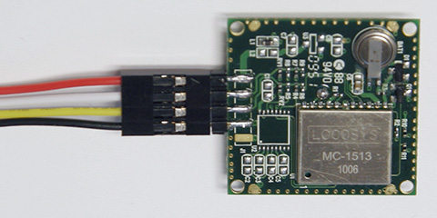
The UART needs 4 wires GND G, VCC V, Transmitted Data (TxD), and Received Data (RxD). The problem is, it is never clear if this is written from the perspective of the sensor or of the microcontroller. Color coding the wires is not so easy either, because the transmit pin of the sensor should be connected to the receive pin of the microcontroller, so if I say yellow is receive - what does this mean? My personal standard is the have the labels always from the perspective of the device. T is always the transmitting pin (output) and R is always the receiving pin (input) - it does not matter if it is the sensor or the microcontroller. I have the colors of the wires depending on the function. White is transmit on the microcontroller and receive on the sensor and yellow is receive on the microcontroller and transmit on the sensor.
The order is similar to the I2C connector and I decided that transmit is closer to the V pin. The order is always the same, but the colors are device dependent, until I can find 2 colored wires...
| # | Layout | Reverse | Who uses it |
|---|---|---|---|
| 1 | G V T R |
R T V G |
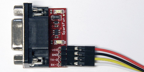
microcontroller side, RS232 Shifter/FTDI Breakout for connecting sensors to a computer |
| 2 | G V T R |
R T V G |
sensor side, RS232 Shifter/FTDI Breakout for connecting microcontrollers to a computer |
The sensor pin layout is only true for sensor PCBs that I create. For 3rd party sensors I have to go with the manufacture's order and just create special cable that reorder the layout.
 |
 |
Power Supply
Providing your project with the right power can be more complicated than it should be. Different plugs, protection from the wrong polarity, regulated or unregulated, etc. Here are some links to read - on Adafruit is Kit Hints and Batteries. On SparkFun is Unregulated Power Supply Tutorial, Background and Power Supply, and Power Supply Protection
After some thought I decided not to integrate a regulated power supply an each and every board. First the +2V can be annoying if I want to go with Batteries after all and the additional space and weight is not so great either. SparkFun offers a great regulated power supplies - a 5V and a 9V version.
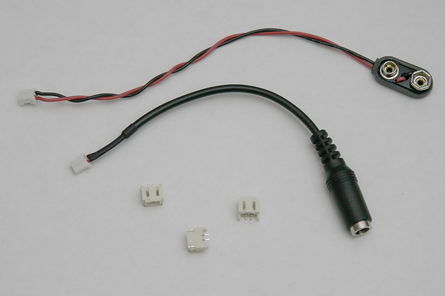
The next decision I made is to give up on the so popular 2.1mm barrel connector. They are really big and not so great for portable devices. I decided to go with a polarized connector, but there are many different types out there with different shapes and sizes. I just decided to go with JST - which makes it easy to use a Polymer Lithium Ion Battery. Here is a 860mAh and a nice little charger from SparkFun.
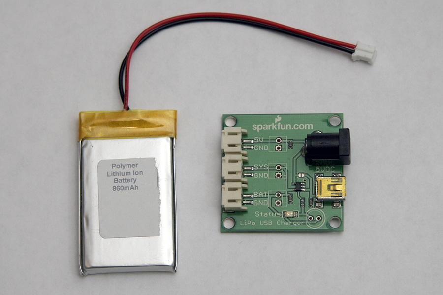
The problem is, that now I had to make or buy little adapters, to make sure I can actually get the power to the project. The barrel jack adapter can be bought from SparkFun which is good for wall warts.
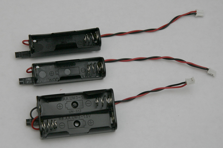
I made the second adapter myself with a 9V Snap Connector and a JST 2-pin SMT connector pack from NKCelectronics. It is great for 9V batteries or 2×AA Battery Holder.
I also recommend the battery pack with regulated output from bodhilabs. It allows you to use one or two regular AA/AAA for your 3.3V or 5V needs. Unfortunately, they do not use JST (they use Molex). It just takes a few minutes to cut of the original plug and solder on a JST though - the JST 2-pin SMT connector pack from NKCelectronics is very helpful.