ATtinyX5 - pov
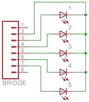
Similar to the original MiniPOV - 5 LEDs connected to all the data pins. Great to learn about programming and just debugging of some code.
Parts List
| 5 | LEDs | generic (I used orange, because the 2.0V is great for battery powered projects) |
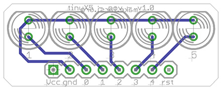
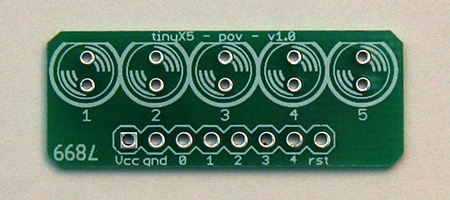
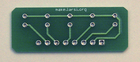
| 1 | PCB | |
| 1 | board | |
| 1 | bridge |
For red/orange/yellow LEDs and 3.3V use 100Ω ¼W resistors - brownblackbrowngold For red/orange/yellow LEDs and 5.0V use 220Ω ¼W resistors - redredbrowngold |
 |
 |
 |
 |
Code
All the code be downloaded from here.
#include <avr/io.h>           // this contains all the IO port definitions
#include <util/delay.h>

#define DELAY 625             // 625ms * 32 = 20 seconds

int main (void) {
  DDRB = 0x1F;                // output: 0, 1, 2, 3, 4

  while (1) {
    for (int i = 0; i < 32; i++) {
      PORTB = i;
      _delay_ms(DELAY);
    }
  }

  return 0;
}
#include <avr/io.h>           // this contains all the IO port definitions
#include <util/delay.h>

#define DELAY 125             // 125ms * 8 = 1 seconds

void display(int v) {
    PORTB = v;
    _delay_ms(DELAY);
}

int main (void) {
  DDRB = 0x1F;                // output: 0, 1, 2, 3, 4

  while (1) {
    display(0x01);
    display(0x02);
    display(0x04);
    display(0x08);
    display(0x10);
    display(0x08);
    display(0x04);
    display(0x02);
  }

  return 0;
}